Chair Plans, Patterns, and Builds · the Keel pattern · truss line
Keel Truss Lounge Chair
The same two triangles with the apex moved from the seat to the arm: ten sticks, pinned, no notches and no glue.
Free to build, copy, change and sell. The drawings and plans are licensed Creative Commons Attribution 4.0 (CC BY 4.0): credit Karl T. Ulrich, hundredyearchair.com.
A record of the third build (4 September 2026) more than a settled pattern. The arm cap length is a placeholder, and whether the keel goes from 18 to 25 mm is an open upgrade.
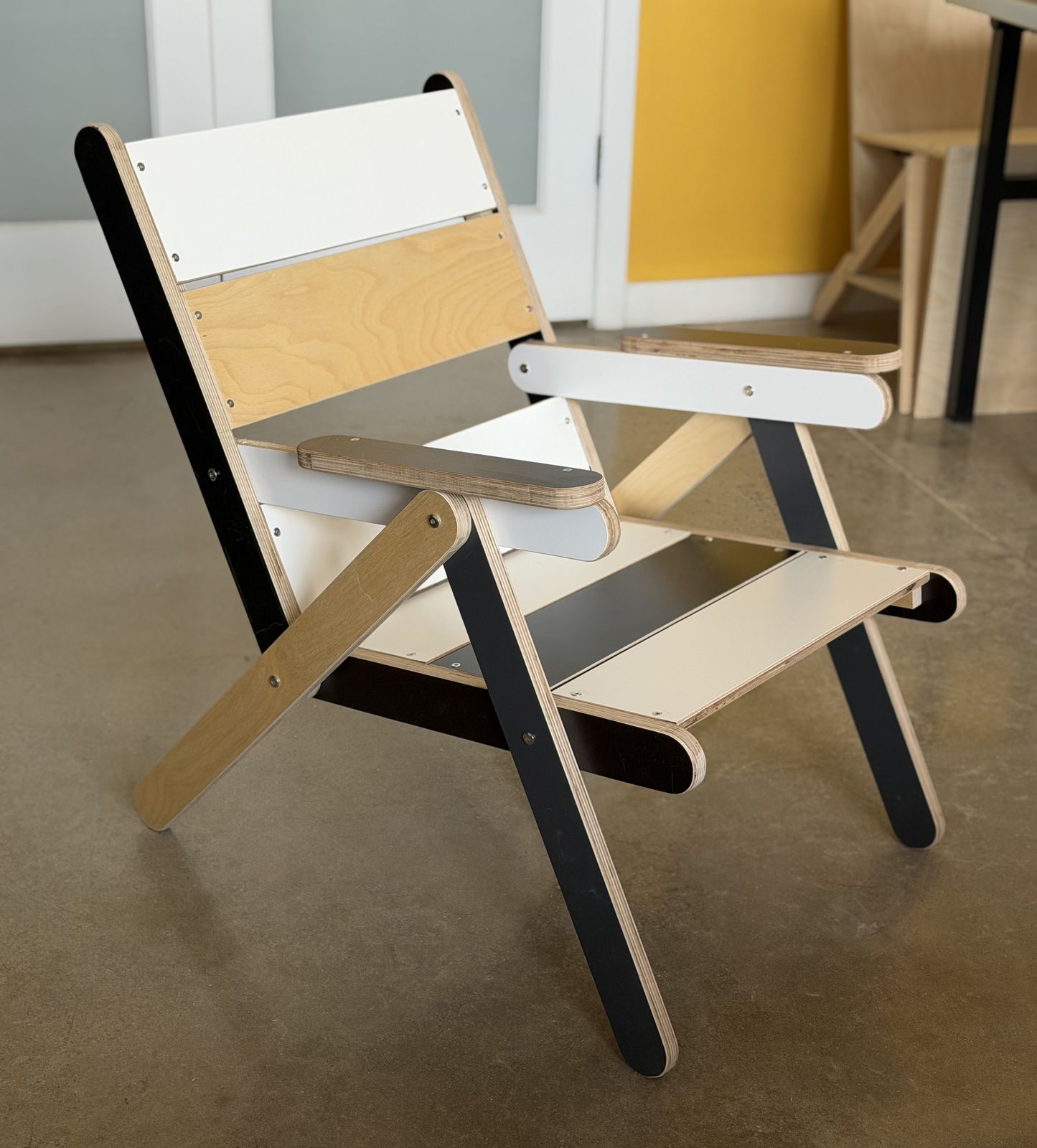
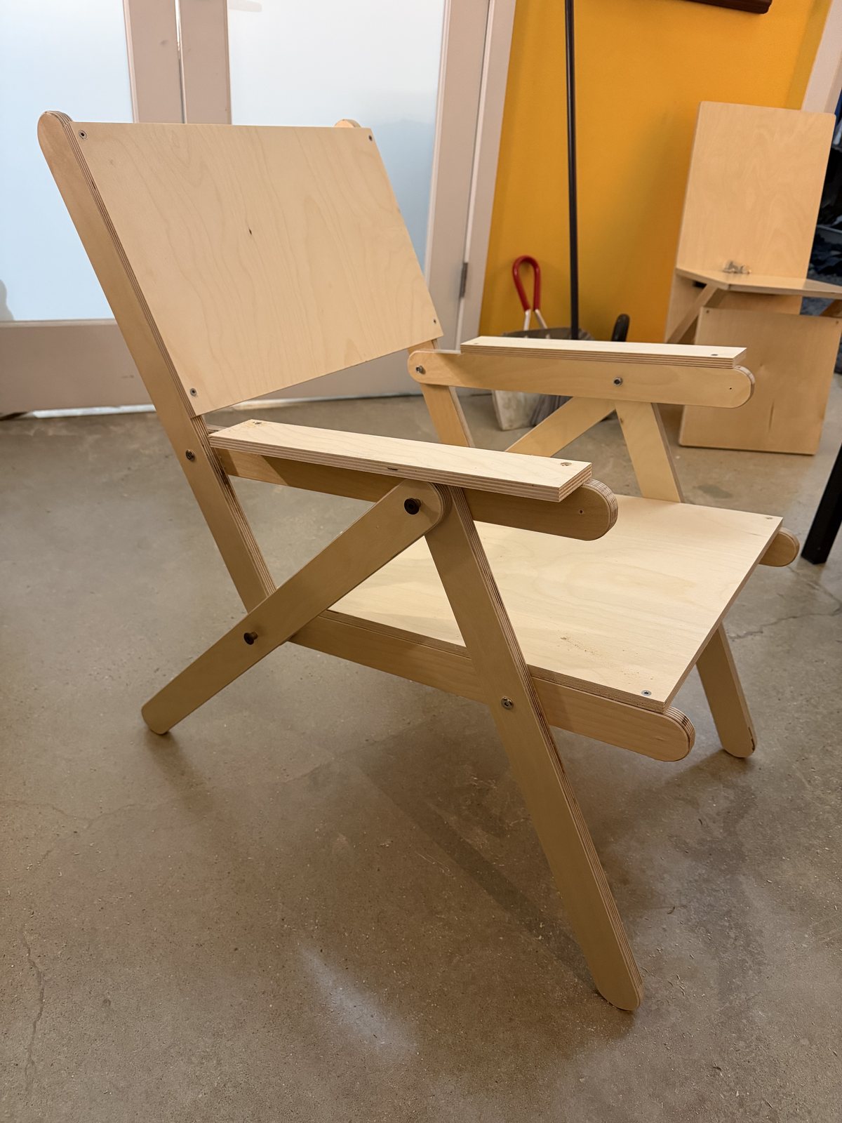
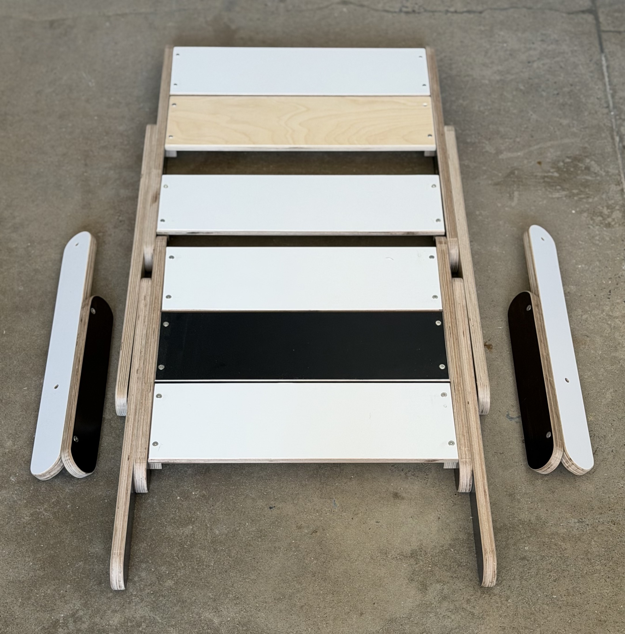
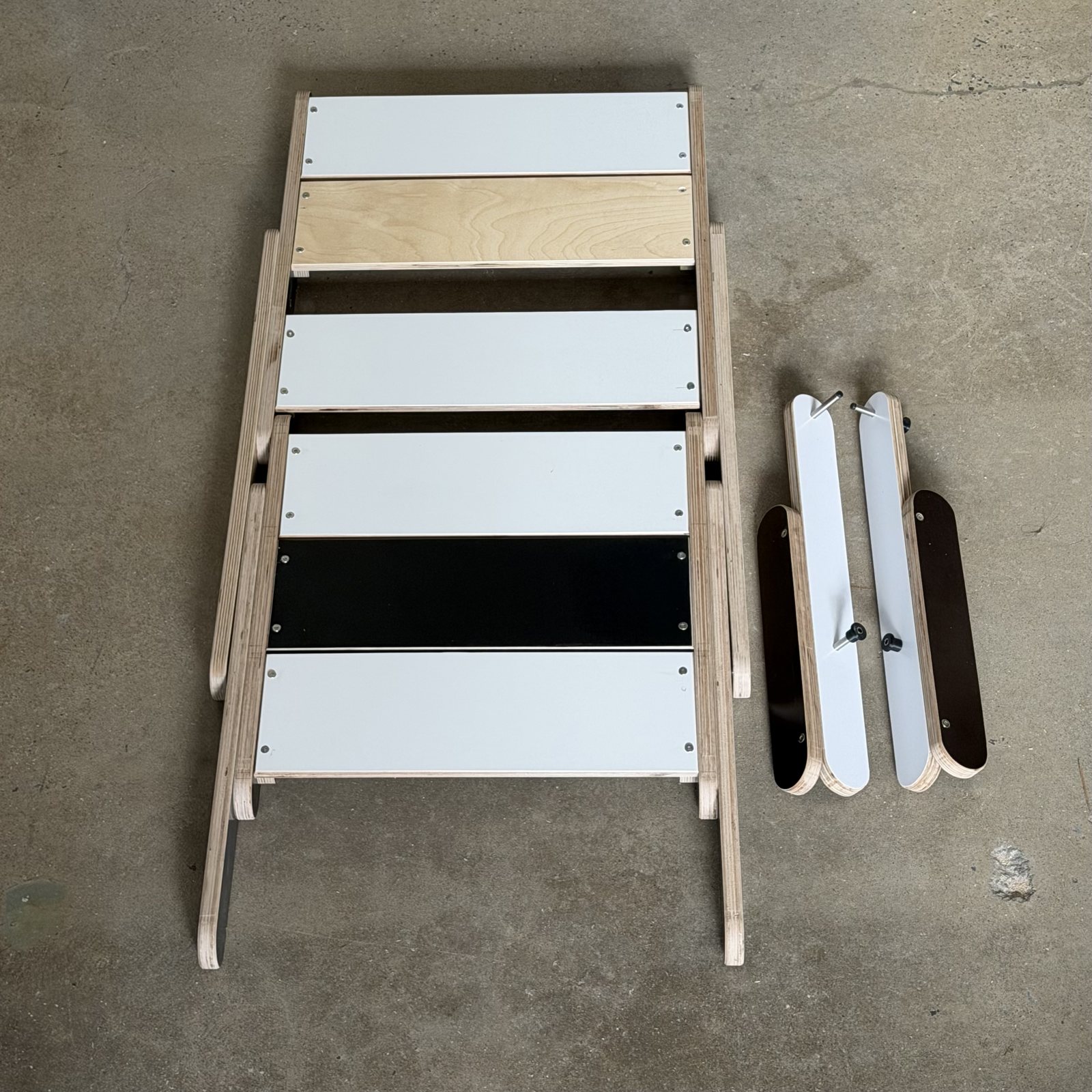
The chair
This is the second chair built to the Keel pattern, and the one that kept a promise the project made at the start and had stopped keeping: that the chair could come out of the scrap pile. The Keel Panel wants a 400 mm panel. The widest piece in this one is 143.
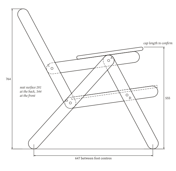
The topology is the Keel Panel's. Two congruent triangles share a keel, and the keel is the only member that belongs to both. What moved is the apex: in the Keel Panel it is where the seat meets the back, and here it is where the arm meets the back. That relocation turns four panels into ten sticks and every notch into a pin. Set the seat-to-back angle to 90 degrees plus half the apex and the keel's pin spacing equals the arm and seat spacing, which is why ten sticks need only four cut lengths and two drill settings.
Drawings
Cut list
| Part | Name | Qty | Length | Pin to pin | Note |
|---|---|---|---|---|---|
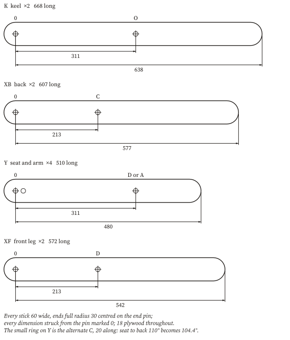
| K | keel | 2 | 668 | 311 | pins at A and O; foot at the far end |
| XB | back | 2 | 607 | 213 | pins at O and C |
| Y | seat and arm | 4 | 510 | 311 | seat: O and D; arm: C and A; alternate C at 20 |
| XF | front leg | 2 | 572 | 213 | pins at A and D; foot at the far end |
| arm cap | 2 | to confirm | 60 wide, 18 thick, R30 | ||
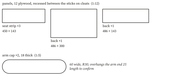
| seat strip | 3 | 450 | 143 wide, 12 ply | ||
| back panel | 1 | 486 | 300 wide, 12 ply | ||
| back panel | 1 | 486 | 143 wide, 12 ply |
Stock. About 6 m of 60 mm strip in 18 mm plywood for the sticks, plus 12 mm plywood for the panels and a few hardwood cleats. Mixed colours and species are the point.
The inch plan. The sticks stay 18 mm plywood (23/32 for the eye) and the panels 12 mm. The pin spacings are the design's whole millimeters converted to the nearest sixteenth, so they differ from the millimeter plan by less than 0.4 mm.
Hardware. Eight barrel bolts (sex bolts): four long for the three-layer stacks, four short for the two-layer stacks. Small screws for the panels and cleats. Size the holes to the bolt and drill them square.
Building it
- Cut ten sticks from 18 plywood strips 60 wide: two keels, two backs, four seat-and-arm sticks and two front legs. This is what the scrap bin is for; the widest piece in the chair is a 143 panel strip.
- Round every end to a full 30 radius centred on its pin. A printed router guide with a small hold-down hole at the radius centre does this in one pass per end and puts the pin centre where it belongs.
- Drill the pins. Every stick is dimensioned from the pin at one end, marked 0 on the parts sheet. Two settings do the whole chair: 311 on the keels and all four seat-and-arm sticks, 213 on the backs and front legs. A third, 20, is the optional alternate C on the four Y sticks. Make a drill template; holes laid out by hand let the joints wobble.
- Lay up each side in three layers: the keel outside, the back and front leg in the middle, the arm and seat inside. Pin O takes keel, back and seat; pin A takes keel, front leg and arm; pin C takes back and arm; pin D takes seat and front leg. The two triangles share the keel and nothing else.
- Use barrel bolts, eight in all: four long through the three-layer stacks at O and A, four short through the two-layer stacks at C and D. The first build used plain M6 bolts in 6 mm holes.
- Screw hardwood cleats to the inside faces of the seat and back sticks. Drop the panels between the sticks, flush with their top faces: three seat strips 143 × 450, and back panels 486 × 300 and 486 × 143. Screw down through each panel into its cleat, one screw size, one inset, evenly spaced.
- Pin on the arms last. They do not fold with the rest of the frame, so they ship loose. Each carries a cap 60 wide and 18 thick, overhanging the arm end by 25.
- To fold the chair, pull the keel pin at the apex: the remaining parallelogram lies down flat.
Open and estimated
- The arm cap length is not settled; the drawing marks it.
- Panels on top of the sticks rather than recessed between them would raise the seat 12 mm; the frame, sticks and pins are identical either way.
- A 25 mm keel is a stiffness upgrade over 18 (flex roughly halves), and only the long bolt changes.
- The pin joints in plywood have a little play when the holes are drilled by hand; bushings or a drill template are the cures under consideration.
Further: So Similar, Yet So Different, the chapter · The Centaur, where the packing is worked out.
Designed by Karl T. Ulrich. The drawings are generated from tools/make_k3_popsicle_v3.py, the same geometry the sticks were cut from. Plan of 2 October 2026. Every drawing on this page is generated from the same parameters as the PDFs and the cut list, by tools/make_plans.py. Drawings and plans by Karl T. Ulrich, hundredyearchair.com, licensed CC BY 4.0: free to copy, adapt, build and sell, with attribution.