Chair Plans, Patterns, and Builds · the Keel pattern · panel line
Keel Panel Dining Chair
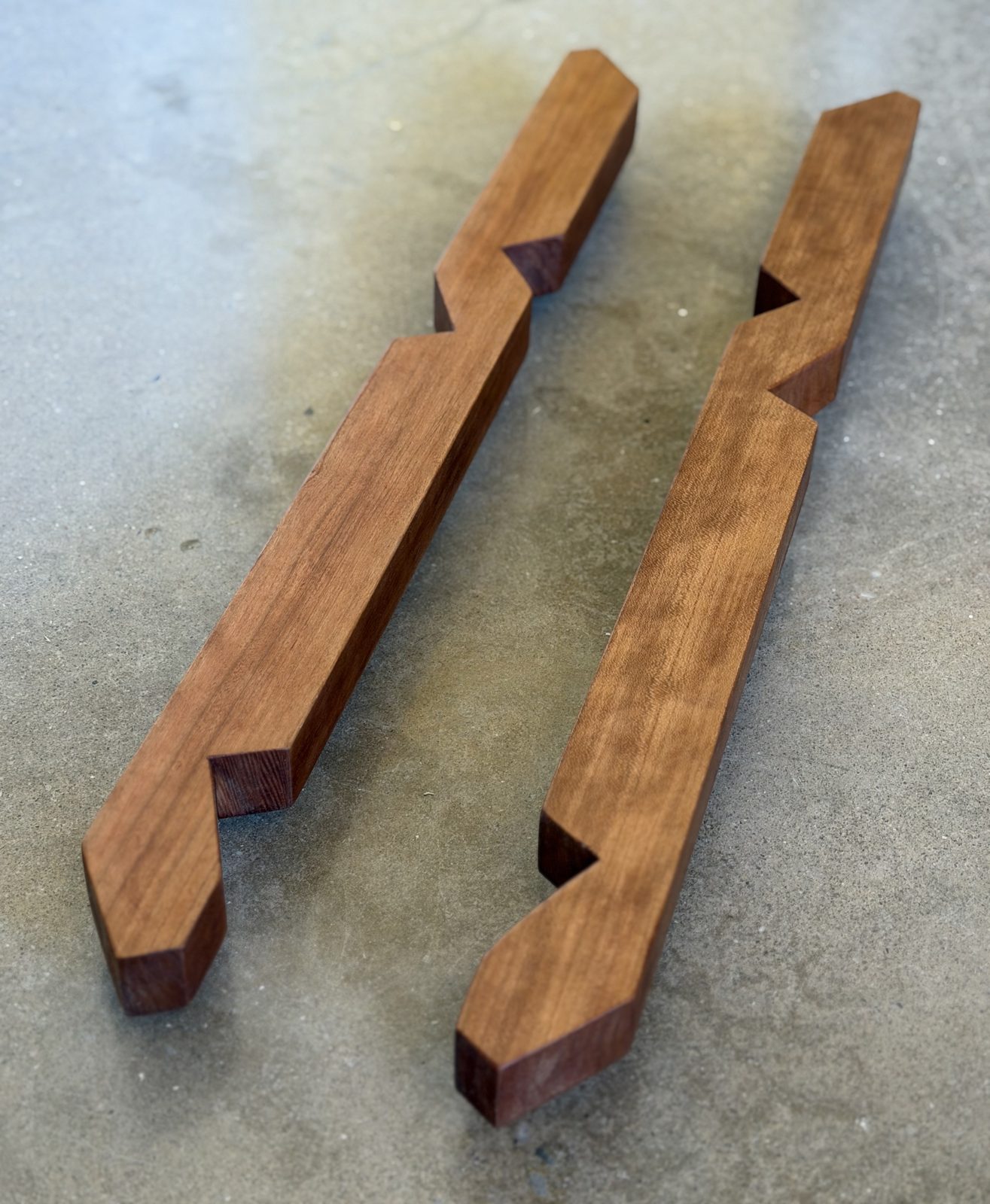
Two hardwood keels, three plywood panels and a pair of front legs: two congruent triangles sharing a keel, with fish mouths in place of blocks.
Free to build, copy, change and sell. The drawings and plans are licensed Creative Commons Attribution 4.0 (CC BY 4.0): credit Karl T. Ulrich, hundredyearchair.com.
The front is drawn here as a pair of legs, as the recent chairs are built. The frame analysis (TN-9) was solved for a full front panel and has not been rerun for legs.
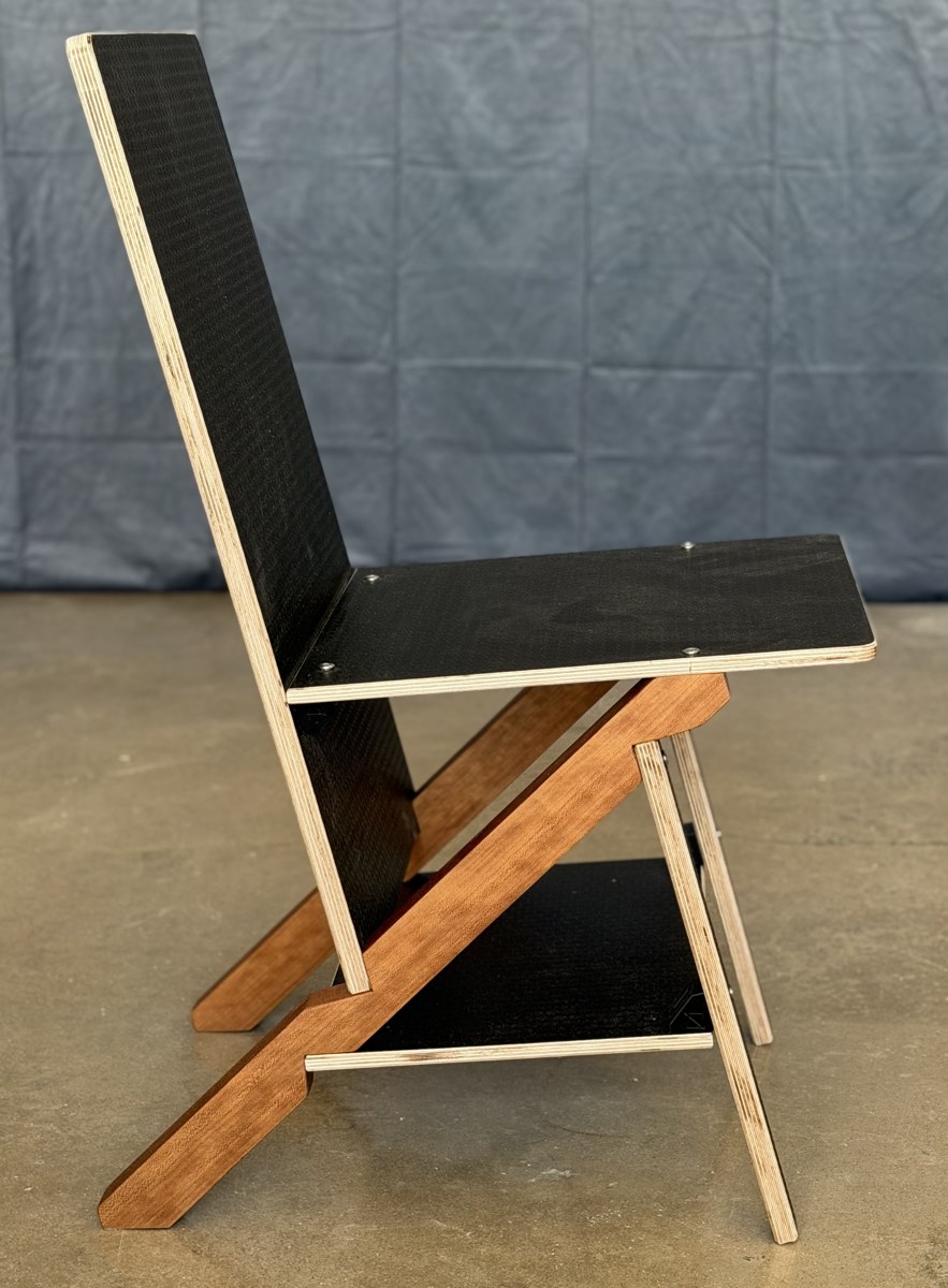
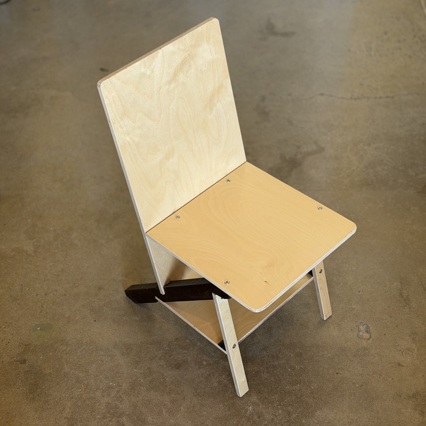
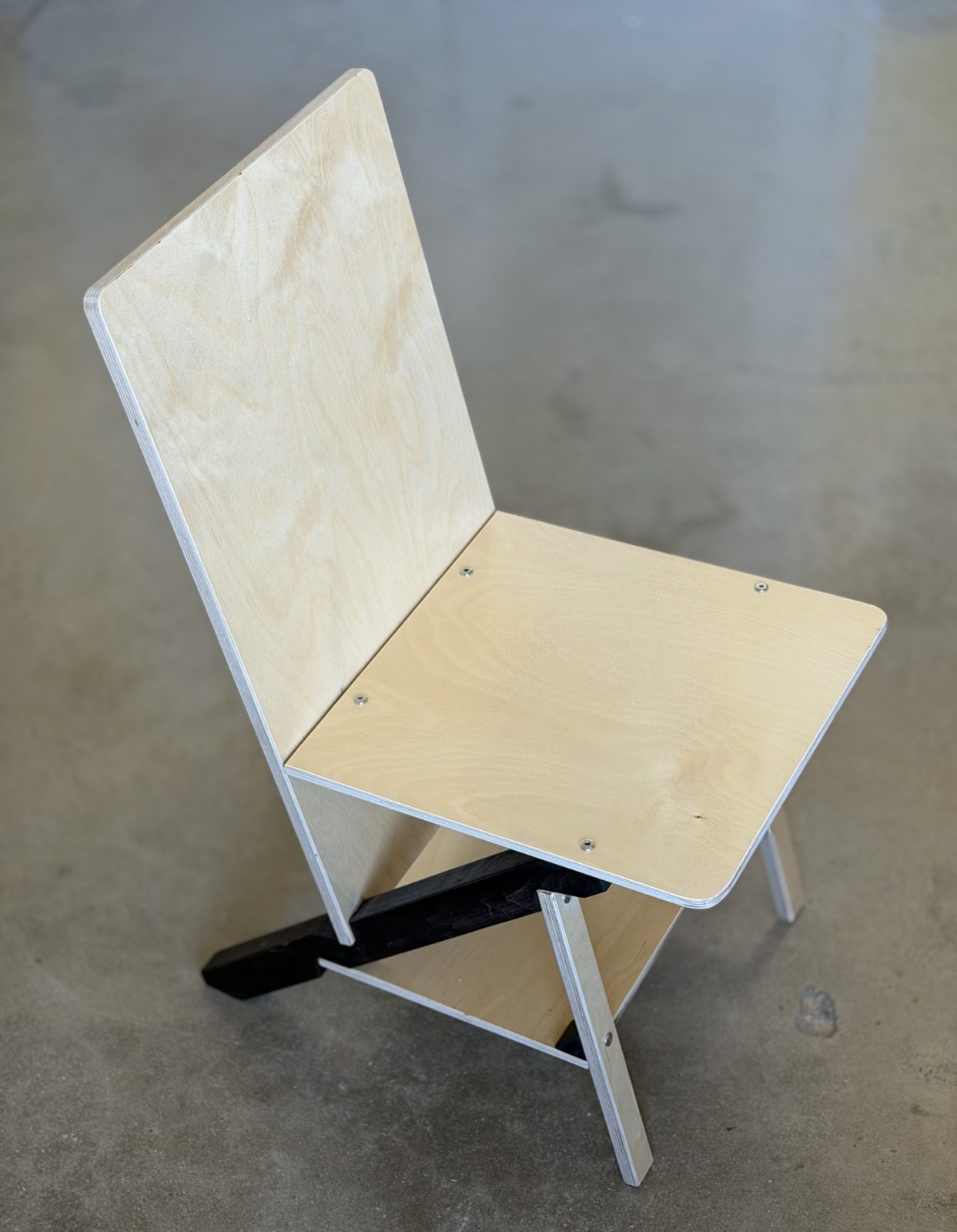
The chair
This is the chair in the form I would build again. Earlier versions carried the load on twelve glued blocks; this one trades them for a keel, one solid member per side, cut once to a drawing, that carries every hard joint in the frame as a notch. The geometry underneath does not move: two congruent 40-60-80 triangles sharing the keel line, with sides 219, 295 and 335 mm and the two triangles set 70 mm apart along the keel. Every vertex-to-vertex distance in the chair is one of those four numbers.
The keel does the locating and the panels are scribed to fit it. A scribed member is by definition the length of the gap it fills, which is why almost none of this chair has to be measured accurately. If the keel is the part you would rather not cut, it is the part a kit would supply; either way, the rest is straight cuts and a few screws.
Drawings
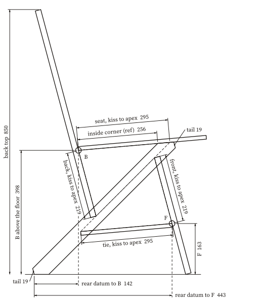
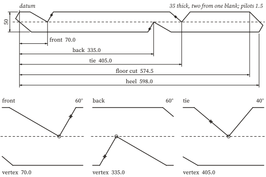
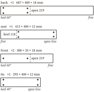
Cut list
| Part | Qty | Stock | Length | Width | Note |
|---|---|---|---|---|---|
| Keel | 2 | hardwood | see the keel layout | 50 × 35 | cut the pair from one stacked blank |
| Back | 1 | 18 ply | 687 | 400 | 219 side, opposite 40°; runs on above the seat |
| Seat | 1 | 12 ply | 413 | 400 | 295 side, opposite 60°; nose runs past the keel kiss |
| Front leg | 2 | 18 ply | 388 | 35 | 219 side, opposite 40°; foot runs on below the tie |
| Tie | 1 | 12 ply | 295 | 400 | 295 side, opposite 60°; kiss to kiss, the one member in tension |
Stock. About a tenth of a 2400 × 1200 sheet of 18 mm structural plywood and a tenth of a sheet of 12 mm, plus two keel boards of dense hardwood, 50 × 35, salvaged if you have it.
The inch plan. The panel stock stays 18 and 12 mm plywood, since that is what is sold; the nearest 32nd of an inch is given beside it for the eye only. Every chosen value (keel section, wing, hole setback, panel width) is an exact inch size, and only the derived lengths round to the sixteenth, by 0.6 mm at most.
Hardware. Four apex brackets; four M6 × 30 and four M6 × 25 bolts with eight thin nuts (10 across the flats, 3 thick); wood screws, about 4 mm, as keepers and four on the tie. The keel pilots serve either an M6 furniture bolt into a threaded insert or a plain wood screw, so the pattern does not pick your hardware.
Building it
- Cut the five flat parts: the back and the two front legs from 18 mm structural plywood, the seat and the tie from 12 mm. Every cut is straight and square; the two 80 degree apexes kiss square and are closed by brackets, not mitred. Nest each panel with its length along the face grain and say so on the part.
- Make the two keels as one. Stack two boards, lay out once, cut once, separate. The two keels are the same part translated across the chair, not a mirrored pair, and identical by construction is what squares the chair.
- Strike every keel station from the keel's own end, the corner where the seat bevel runs out: 70 to the front station, 335 to the back, 405 to the tie. Nothing accumulates when everything is struck from one datum.
- Cut the three fish mouths. Each is a right angle at its vertex, 25 in from its own edge. Drill 1.5 through the vertex, then saw both faces down to the hole; the drilled vertex leaves a small fillet in the inside corner, where you want one.
- Trim both keel tails with one saw setting, a cut parallel to the back (60 degrees to the keel), leaving an end face of about 19. A 40 or 45 degree wooden point chips on the first knock.
- Drill the holes from the parts sheet. At the keel, pilots two per panel end, 20 along from the seated end and 18 in from each side edge; a front leg takes one on its centreline. At each apex, one bore per member per bracket, 20 back from the apex, drilled 6.5 clear so the bolt pulls the member onto the flange.
- Make or buy four apex brackets: a hollow 80 degree section, the chair's own apex angle, with a nut channel in each flange. The printed prototype (ASA) and its STEP and STL files are on the site; the production part is an aluminium extrusion. At the seat and back apex the bracket centres sit 50 in from each side edge; at the tie and front apex each bracket is centred on a front leg.
- Dry fit. Set the two keels parallel at seat width, seat each panel end in its mouth, and check that each lands where its kiss says. Scribe any panel that runs long. A snug seat, not a forced one.
- Close in this order: keel and back, the seat across the top, the front legs, and the tie last. The seat and back ride on one face of the keel, the front and tie on the other, which is why the front and back never meet.
- Fasten. The tie is the only member in tension, about 500 N under a seated load, so it takes two screws at each end. Every other screw is a keeper that holds a compression joint shut against handling, one or two per joint. Away from the drawn holes, keep screws 30 from a panel end. At the apexes, four M6 × 30 and four M6 × 25 bolts with thin nuts.
- Stand it on a flat floor, check for rock, and trim the proud foot rather than shimming.
- Finish with something renewable in place, a wiping varnish or a hard wax-oil, and write each part's dimensions on its underside so the next rebuild reads its cut list off the chair.
Open and estimated
- The bracket spacing at the seat and back apex is drawn as bracket centres 50 in from each side edge. If it was meant as 50 to the near edge of the bracket, every seat and back apex bore moves out by half a bracket. Check before drilling four panels.
- The deeper 25 mm fish mouths rest on an argument, not a test: the governing case is the cantilever below the tie station, which keeps the full 50 mm. Nobody has broken one.
- The formal conformance protocol (seated load cases, the lateral shove, the tip rules) publishes with the first stable release. Until then: build it, sit in it, lean back hard, and wiggle a free leg.
Further: the apex bracket, STL · the apex bracket, STEP · TN-9, the keel · the configurator · The Keel, the chapter · Appendix: The Keel Pattern.
Designed by Karl T. Ulrich. The three drawings are generated from the project's Keel geometry (tools/k2_parts.py, k2_geom.py) by the same scripts that cut the chair. Plan of 2 October 2026. Every drawing on this page is generated from the same parameters as the PDFs and the cut list, by tools/make_plans.py. Drawings and plans by Karl T. Ulrich, hundredyearchair.com, licensed CC BY 4.0: free to copy, adapt, build and sell, with attribution.