The Hundred-Year Chair · back matter
Appendix: The Pattern
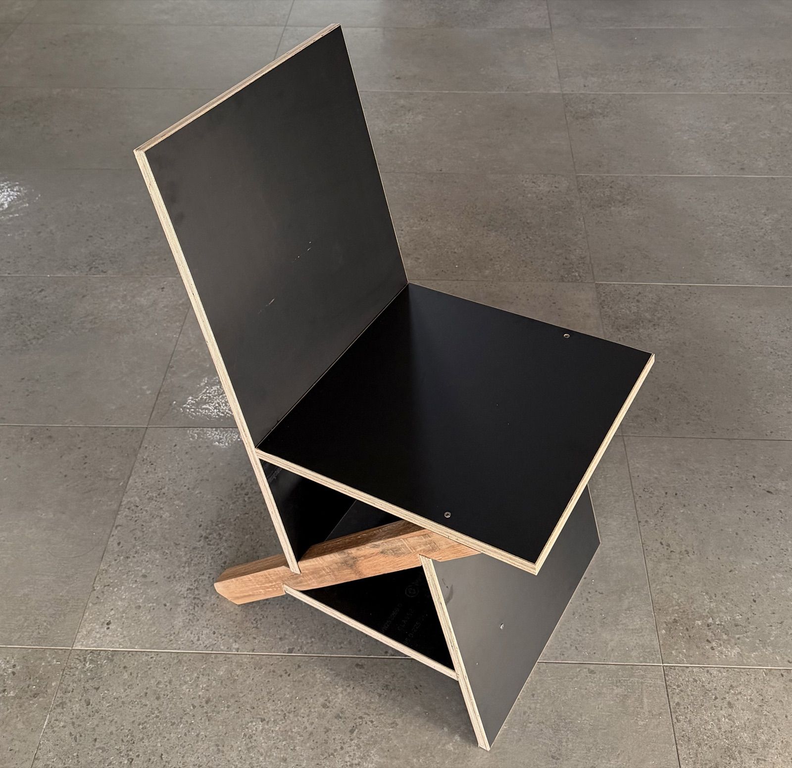
A book that argues objects should outlive their makers has one obligation it cannot delegate to a website. This appendix is the pattern: enough to build the chair from the book alone, with no server answering. The living version, with the printable templates, the configurator, and the corrections as they accrue, is at hundredyearchair.com. But the site is a service and this page is an artifact, and if you are reading this after the service has stopped, what follows is sufficient. That is not a boast; it is the design requirement this appendix was written to.
The Keel pattern
What follows is the chair in its keel form, the one on the cover. It assumes a saw, a drill, and patience, and nothing else. The geometry first, because the geometry is the chair: two congruent 40-60-80 triangles sharing a keel line, and four numbers that generate everything: 219, 295, and 335 millimeters, the triangle's sides opposite its 40, 60, and 80 degree corners, and 70, the separation of the two triangles along the keel. Every vertex-to-vertex distance in the chair is one of these. The posture they deliver is the one frozen in the first week and never moved: seat at 440 with a 5 degree pan, back raked 15 degrees, a 100 degree seat-back angle.
Three drawings carry the whole of it, and they are the three to print. The chair assembled, so you know what you are aiming at. The keel, which is the only part that asks for care. And every panel laid flat, which is what you take to the saw. All three are generated from the same geometry that cuts the chair, so they cannot quietly disagree with it.
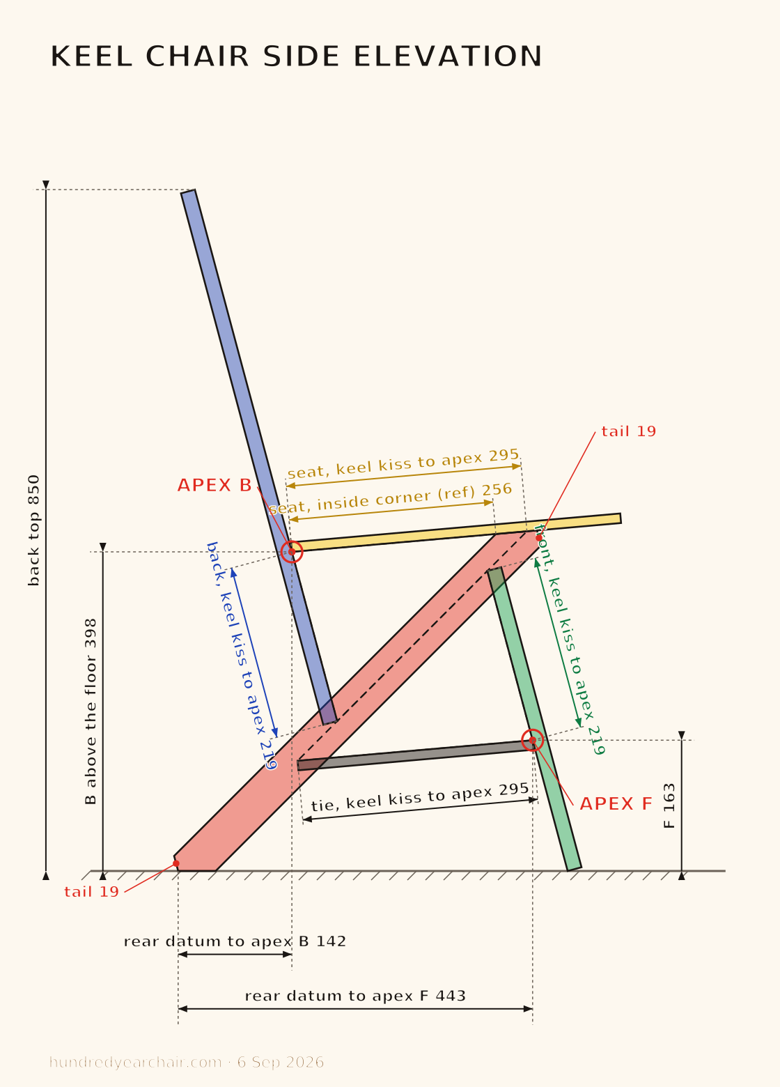
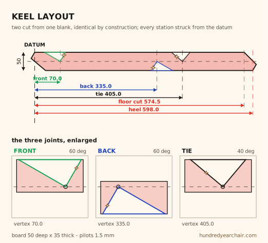
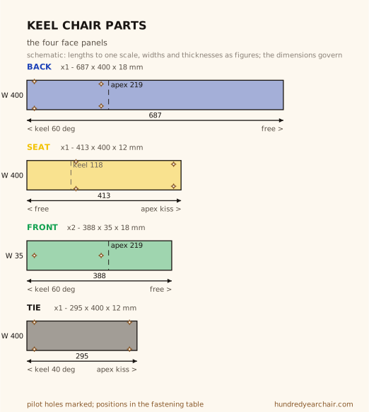
Seven parts: two keels, three flat panels and two front legs.
| Part | Qty | Stock | Blank | Triangle side |
|---|---|---|---|---|
| Keel | 2 | dense hardwood, 50 x 35 | cut to the layout below | 335, twice |
| Back | 1 | 18 ply, 400 wide | 687 | 219 (opposite 40 deg) |
| Seat | 1 | 12 ply, 400 wide | 413 | 295 (opposite 60 deg) |
| Front leg | 2 | 18 ply, 35 wide | 388 | 219 (opposite 40 deg) |
| Tie | 1 | 12 ply, 400 wide | 295 | 295, kiss to kiss |
A whole chair takes about a tenth of a 2400 by 1200 sheet in each thickness, plus the two keel boards, salvaged if you have them. Run every part's length along the face grain and write the grain direction on the part. The only angled cuts are the two 80 degree apex cuts where seat meets back and tie meets front, ten degrees off square, a run of about 2.1 millimeters across the twelve millimeter thickness. Everything else is straight and square.
The keel is the whole precision budget. Get it right and every other part is scribed into a gap that cannot be wrong. Measure everything from one physical corner a tape can hook, the end of the front-and-tie edge, where the bevel the seat beds on runs out. From that datum the three joint vertices sit at 70 (front), 335 (back) and 405 (tie), which are the pattern's own numbers: three stations struck from one end, nothing accumulating. Each joint is a fish mouth with a right angle at its vertex, its two walls being the mating panel's own face and square end, and the vertex sits 25 millimeters in from the edge at every station. At 25 and 25 on a 50 board the two kiss lines land on the same line, so the two triangles share one line exactly. Strike the vertex, drill 1.5 millimeters through it, and saw both faces down to the hole; the drilled hole stops the cut and leaves a small fillet exactly where an inside corner wants one. Cut both keels from two boards stacked, then separate them. They are the same part, not a mirrored pair, and identical by construction is the property that squares the chair. Both ends of the keel come to an acute point, and both points are trimmed off parallel to the back, which is 60 degrees to the keel, leaving an end face of about 19 millimeters. The foot is cut flat to the floor and keeps about 47 millimeters of contact.
Assembly is an order, and the order matters. The two triangles ride on opposite faces of the keel: seat and back notches on one face, front and tie on the other, which is why the front and back never meet and why the closed chair clamps the keel between its triangles. Set the two keels parallel at seat width and dry-fit everything. Close in this order: back first, then the seat across the top, then the front, and the tie last. Scribe any panel that runs long; a snug seat, not a forced one, is the target. Then the fasteners, and here the structure does most of the arguing. Under a seated load every joint but one is compression the load itself keeps closed. The tie is the one member in tension, about 500 newtons of pull at working load, so the tie gets real screws, two per end, four in all, each carrying about 250 newtons of shear, well inside a 4 millimeter screw's capacity in this ply. Every other screw is a keeper, holding a compression joint shut against handling and the day someone drags the chair by its back: one or two per joint by eye, every screw at least 30 millimeters from a panel end. Glue is optional, and if you use any, use a reversible one, because a joint that can be opened is the maintainability this book spent three chapters on. Set the chair on a flat floor, check for rock, and trim the proud foot rather than shimming.
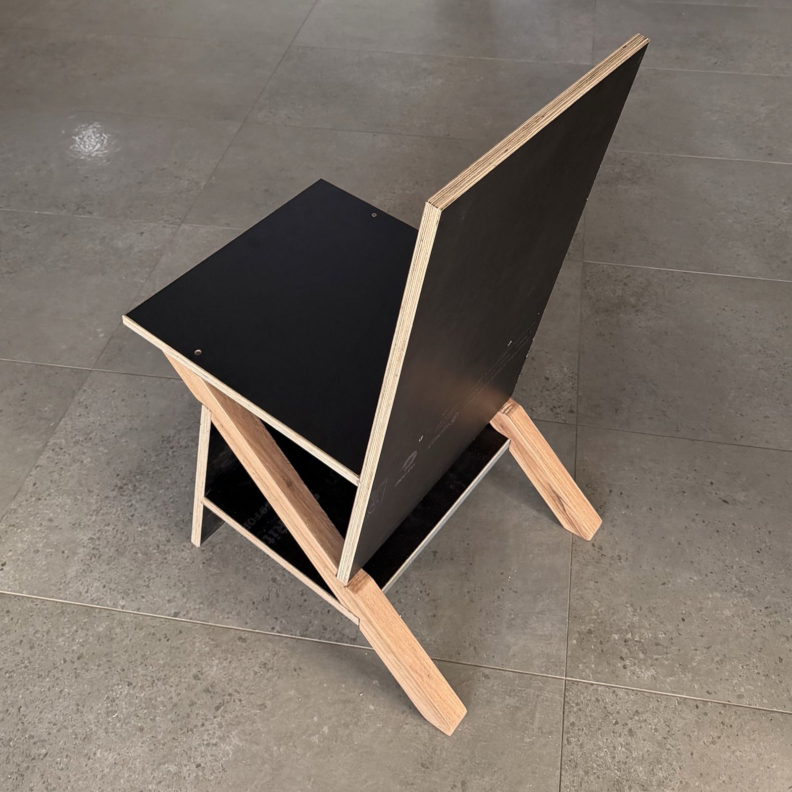
Finish is free at the level of longevity, provided it is renewable: a finish that can be re-coated in place, without stripping, by whoever keeps the chair in fifty years. A wiping varnish or a hard wax-oil both qualify. Then sign it, and write the part dimensions on the underside of the seat in pencil, so the next rebuild can read its cut list off the chair itself, the way I read Rietveld's off his.
One test, in place of a standards document that does not exist yet: build it, sit in it, lean back hard, and wiggle a free leg. If nothing moves, it passes. If something does, the chapter on the verdict of the builds is the debugging guide, and the error you find may be mine. Report it; the pattern is the thing this book actually shipped, and errata are how a pattern stays alive for a hundred years.
I know the requirement can be met because someone met it ninety-two years before me, and I am the proof.
The precedent: Rietveld's Krat, 1934
In 1934 Gerrit Rietveld published his crate furniture as drawings and prices: plain deal boards, screws, a parts list, and costs worked to the guilder, on the explicit premise that the buyer could be the builder. In July 2026 I built his chair from salvaged film-faced plywood for about ten Australian dollars, and it was the first build of this project. The pattern worked at a distance of ninety-two years, which is the entire argument of this appendix conducted as an experiment. And it worked in the way real patterns work: imperfectly, and audibly. His sheet draws the seat cleat at 390 millimeters, and a 390 cleat cannot physically fit between the members that receive it. That is what he designed, and it is a bug no museum visit can find, because the exhibit is already assembled. You find it with a saw, and you cut the cleat shorter. the chapter The Search makes that discovery a method; here it is a warranty statement. This pattern, too, will carry an error a builder finds in some year I will not see, and finding it is part of what the pattern is for.
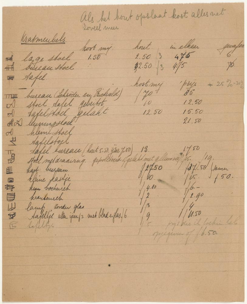
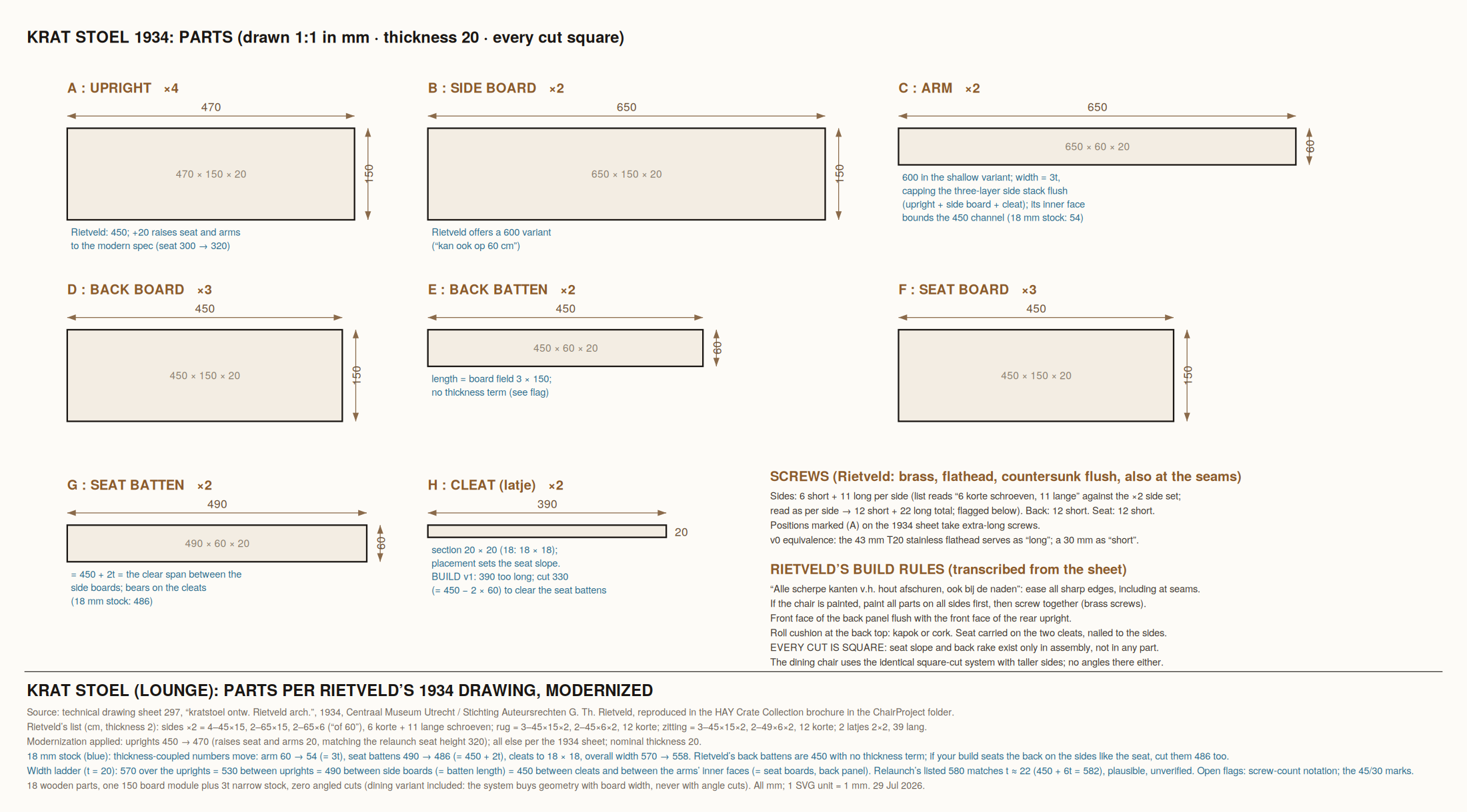
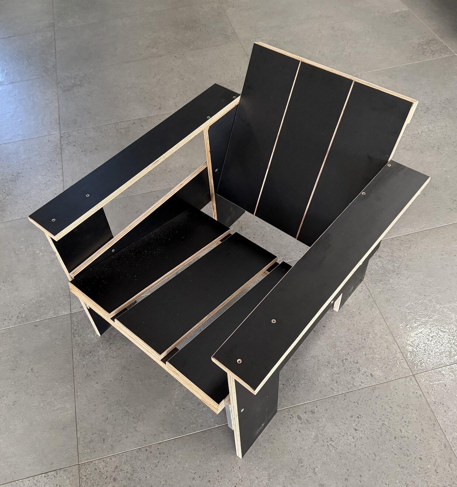
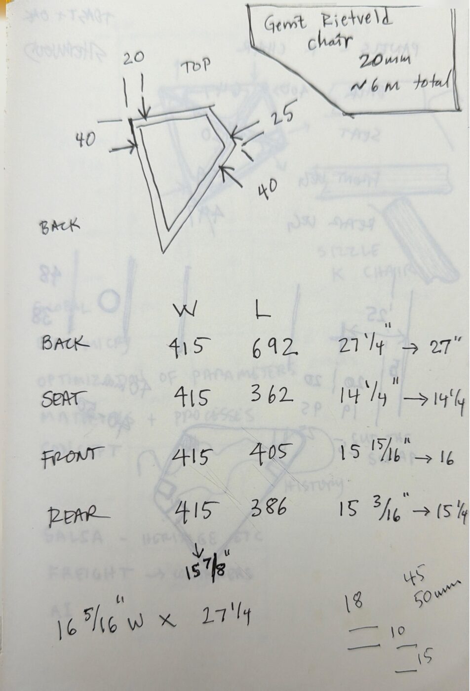
Every K2 dimension on this page derives from the project's geometry files and the keel layout sheet (checked 29 Aug 2026); reconciliation of each figure against the as-built keel chair of 18 August is queued before print, and the tie-tension figure is an engineering estimate flagged on the ledger. The Krat facts (1934 publication, buyer-as-builder premise, the ten-dollar replica) verify in the early chapters' sources. The parts sheet is this project's redrawing of Rietveld's 1934 technical drawing (sheet 297, Centraal Museum Utrecht), with its modernizations declared on the sheet; the cleat is printed at his 390, which does not fit, and the as-built corrected length is queued to be measured off the replica. The Rietveld price list is reproduced from the Rietveld Schroder Archive scan; credit and permission are queued. The three K2 drawings are vector sheets generated by the same scripts that cut the chair, and they carry the date they were drawn.
A chapter of The Hundred-Year Chair, drafted and refined in public. The same text lives in the book; the interactive tools and the fully-sourced technical notes live here. home · the book · the technical notes · hundredyearchair.com