Technical note 8
TN-8: CAD by Conversation
Using a language model to do mechanical CAD. First draft 17 Aug 2026, written from this project's own record: every printed part in the chair, from the first bracket to the barrel nut holder now in the workshop, was drawn this way. Status: DRAFT, a methods note rather than a sourced one.
The claim
For prismatic, parametric parts of moderate complexity, a hand sketch and a conversation now produce a valid STEP file in minutes, where the same part costs hours in a direct manipulation CAD system. The bottleneck has moved. It is no longer operating the software; it is communicating design intent, and nearly every failure in this project's CAD has been a failure of intent rather than of geometry.
KU's assessment, and it matches the record here: this has only been possible in the last twelve months or so. [ASSESSMENT, not a verified claim.]
Why it works: CAD is code
A solid model is a program. In script CAD it is literally Python; in a direct manipulation system it is a feature tree, which is a program with a mouse for a keyboard. Language models are good at code, so the model is not drawing the part, it is writing a program whose output is a solid, then running it, looking at the result and revising the program. The loop is the same one that makes a model useful at software, and it arrives in mechanical design with the tooling already built.
Two consequences follow immediately. The part becomes parametric for free, because it was always numbers. And the design becomes diffable, versionable and reproducible, which matters more to this project than convenience: a STEP file is a photograph of a part, while the script is its genome.
The whole argument in one component
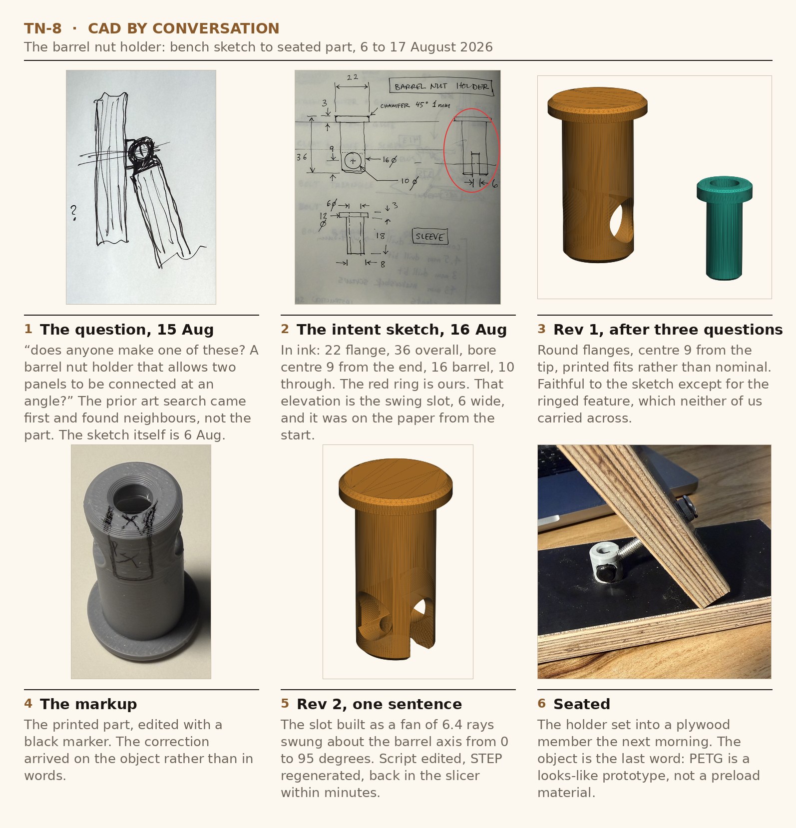
Read the strip as a chain of custody for one idea. The intent survives the sketch, survives the questions, and is then dropped in the one place nobody watches: the reading of a drawing that had already said it. The slot is in panel 2, dimensioned, and it is missing from panel 3.
The exchange, verbatim
This is the whole of it, from the project's own record. KU's turns and the model's turns are quoted as written; the only edits are marked ellipses where a long reply is excerpted, and the bracketed notes naming the attachments.
KU, 15 August 20:41 UTC [with the idea sketch, drawn 6 August]
does anyone make one of these? A barrel nut holder that allows two panels to be connected at an angle? Isn't this the IKEA design we need?
The model [prior art search, excerpted from a much longer reply]
The barrel-nut holder: close neighbors exist, but I can't find your exact part. What your sketch shows is specific: the barrel nut lives in external hardware that hooks over the caught panel's end, so that the angled panel needs zero drilling, the caught panel needs one through hole, and the angle between them is set by the bolt axis rather than by the fitting. [...] So the gap your sketch sits in appears real: an angled, detachable, load-rated panel connection with no proprietary machine, no edge bore, one drill hole total. [...] a deeper patent-and-catalog verification pass goes on the queue before we claim novelty anywhere public.
KU, 16 August 10:22 UTC [with the intent sketch, panel 2]
I'm going to try the barrel nut connector I envisioned yesterday. One will insert throuhg a panel and hold the barrel nut. The other is just a sleeve for the M6 bolt. Please create two STEP files for these two parts. Ask me questions if ambiguous. I'm going to 3D print these.
The model, the three questions, before generating anything
Are the flanges round or square? The elevations read either way.
Where does the Ø10 barrel bore center sit? I read the dotted line as the exit face of a 17.5 panel, putting the center 29.5 from the flange top: 3 flange + 17.5 panel + 9, leaving a 1.5 wall below the bore at the 36 tip.
Print at nominal dimensions or with fit clearances? Printed holes come out small and shafts proud, so exact 16 in a 16 drill bore will not insert.
KU's answers
Round. [...] overall length is 36. The centerline of bore is 9mm from end. [...] Fit clearances.
The model, as built
Center 9 from the tip it is (27 from the flange top). [...] the holder is a Ø22 round flange, 3 thick with the 1mm 45 degree chamfer, on a Ø15.8 shaft (fit for your Ø16 bore), 36 overall; the Ø10.2 barrel bore runs clean through with its center 9 from the tip, and a Ø6.4 bolt bore enters from the tip into the barrel, with a small entry chamfer and a 1mm insertion chamfer on the tip. The sleeve is Ø12 flange, Ø7.8 shaft (for a Ø8 bore), 18 under the head, Ø6.4 through. One thing to check on the printed article: with the barrel that low, the wall under it is about 4mm, so if the first fit is loose in the bore, the fix is filament-cheap, but if the barrel cracks the tip under torque, tell me and I'll thicken the tip or raise the center.
KU, 16 August 19:31 UTC [with the sketch and the printed pair, panel 4]
Oops. We forgot the slot to allow the 6mm bolt to swing 80 degrees to 40 degrees. Let's just put a 6mm slot to allow 90 degree swing there. Revise STEP file and I'll reprint.
The model, rev 2
The printed pair look right, and yes, the bolt has to arrive at the joint angle, not down the axis. [...] The slot is built as a fan of Ø6.4 rays swung about the barrel axis from 0 degrees (the original axial exit through the tip) to 95 degrees (just past square, so the 80 degree corner has margin), all on one side. Two things to know at the bench: the barrel goes in with its thread hole facing the slot side, and since the slot is single-sided the holder now has a handedness, so orient it when you insert it, with the slot facing the mating panel. The tip loses its full ring where the slot exits, so if the first print feels fragile at the two tip prongs under barrel torque, the next revision can shorten the swing to 35 to 95 degrees, which your 40 to 80 joints actually need, and keep the tip ring closed.
Four things are worth noticing in that tape.
The questions are the product. Each of the three would otherwise have cost a print: a square flange, a bore 20 mm out of place, and a set of holes that no bolt would enter. Note the second one especially. The model did not ask where the bore was, it stated the reading it had taken off the drawing and invited correction, which is a far cheaper question to answer and a far harder one to answer wrongly.
The tolerance question is the one a human would forget. Printed holes come out undersize and shafts oversize, so a nominal model is a model of a part that does not assemble. The answer became Ø15.8 in a Ø16 bore, Ø7.8 in a Ø8, and Ø10.2 for a Ø10 barrel, and the part went in.
The model volunteered the failure mode it had built in: a 4 mm wall under the barrel, with what to say if it cracked. That is the fair exchange for asking it to reason about the object rather than the file.
And the correction is one line long. "We forgot the slot" carried more design information than any amount of CAD instruction would have.
What it costs, from this project's record
The barrel nut holder went from a sketch photographed on the bench to a valid STEP in a single exchange, after those three questions. It printed that evening. Then the failure: the slot that lets the bolt swing to the joint angle was missing, and it had been drawn, dimensioned 6, in the right hand elevation of the very sketch the part was built from. The model did not read the whole drawing, and the human who drew it did not notice the omission in the readback either. KU caught it on the printed article and marked it in black marker. The correction was one sentence and one revision, back in the slicer within minutes.
That is the honest accounting: the method's speed is real, and the failure it produced was not a modelling failure at all. It was a reading failure, on a sketch that had said the thing plainly.
The converged frame took about ten revisions across a day, each one triggered by KU opening the file in his own CAD or slicer and saying one sentence. In a direct manipulation system, by KU's estimate, a single part of this class is a several hour job, and each of those ten revisions would have been an afternoon.
The protocol
- Sketch it by hand. Seconds to draw, a few minutes to fuss over. This is still the densest channel for design intent that anyone has invented.
- Photograph the sketch. Add the three or four numbers that actually matter and say what mates with what.
- Ask the model to state its assumptions and ask its questions BEFORE it generates anything. In the barrel nut holder three questions came back: round flange or square, where the cross bore centre sits, nominal or clearance fits. Each answer would otherwise have cost a print.
- Make it list every feature it read off the sketch, and check that list against the paper before it builds. One line per feature, in the sketch's own words and numbers. This is the step that was missing here, and it is the only one in this list that would have caught the swing slot: it was drawn and dimensioned, and it simply never appeared in the readback.
- Take a STEP, and with it a SHADED RENDER OF THE ACTUAL MESH, not a wireframe and not a drawing of the intent.
- Have the model check the solid numerically: watertight, body count, bounding box, and point in solid for any bore that must go through.
- Open it in your own CAD or slicer. That is the real review.
- Correct in one sentence, adding another sketch when a sentence will not carry it.
- Print it, and let the object arbitrate.
Do not edit the file
The script is the design; the STEP is a build product. Editing the output desynchronises them, and the next regeneration silently destroys the edit. This is the same discipline that applies to generated code, and it is more important here because the edit will look successful right up until the part is rebuilt. If the file is wrong, say what is wrong. The model can fix in a minute what would take an hour to patch by hand, and the fix stays fixed.
What goes wrong, honestly
THE MODEL FLATTERS ITSELF. The worst hour of this project's CAD came from reviewing hidden line projections, which are exactly the images that hide defects: an acute tip surviving as a 30 mm dagger, relief cuts modelled as infinite beams that severed the perimeter they crossed, and a part in three separate pieces pretending to be one. All three were invisible in the drawing and obvious in a shaded render of the mesh. The rule that came out of it: render what you made, not what you meant, and let the man with the slicer overrule the man with the SVG.
BOOLEAN HYGIENE IS FIDDLY. Exact tangencies fail silently in the kernel, so features want sinking a fraction proud and trimming with a clip solid. A local cut must be taken from its own body rather than the whole part, or it severs its neighbours. Both bugs happened here and both were caught by counting bodies, not by looking.
SPATIAL CLEARANCE REASONING IS WEAK. Twice a clearance was checked against the wrong obstacle: the adjacent stave rather than the neighbouring foot that actually blocked the socket.
MANUFACTURABILITY JUDGEMENT IS WEAK. A tilted print was proposed that any printer would reject on sight, and did.
IT READS A DRAWING SELECTIVELY. The swing slot was drawn and dimensioned on the sketch the part was built from, and it did not appear in the solid or in anything the model said about the solid. A model that asks three good questions about a drawing can still fail to enumerate what the drawing contains, and the two failures feel identical from the outside: fluent, specific, confident. Ask for the feature list.
ORGANIC FORM IS OUT OF REACH. Script CAD does fillets well and lofts and blends approximately, so the sculptural version of a part stays a sketch.
AND THE RECURRING FAILURE IS THE UNSTATED DATUM: which face, which end, which corner. It has caused more revisions here than any other single thing, and it is not a modelling problem at all. The mitered cut list of the same week is the same lesson in another key.
What the human contributes
The sketch, the physical judgement, and the arbitration. The most valuable messages in this project's CAD have all been one sentence long: one nut is not going to fit, nudge the strut five millimeters; bore only through the boss, not through all; you really think that would print well stood up on end. None of them is a modelling instruction. All of them are intent.
What makes a good prompt
Constraints and mates, not shapes. Name the datum. Give the numbers that matter and say what each face is for. Ask for assumptions and questions before generation. Ask for the render of the mesh and the numeric checks by default, so that self-verification is part of the deliverable rather than something you have to request after being misled once.
When not to
Class A surfaces, large assemblies, anything where a tolerance stack matters more than the shape, and anything the model cannot verify for itself. The method's strength is the loop; where the loop cannot close, the method is just a confident stranger with a CAD licence.
Revisions
18 Aug 2026: the exchange re-dated against the recovered event stream. The first draft placed the opening question on 6 August, taking the date from the sketch's own EXIF; the sketch is indeed 6 August but KU asked the question with it on 15 August at 20:41 UTC. Times added to each turn now that they are known to the minute.
17 Aug 2026: first draft, from the project record, with the barrel nut holder strip and the exchange transcribed verbatim. The verbatim came from KU's own client scrollback: the session's raw transcript for 14 to 17 August was destroyed by a compaction before it was archived, and this dialogue is the only part of that window recovered. See the transcripts README for the gap and what it means.
Technical Notes of the Hundred-Year Chair: public from first draft, refined iteratively, forever. A claim is VERIFIED, STANDARD, DERIVED, or UNVERIFIED, and says which. The register · the verification ledger · hundredyearchair.com